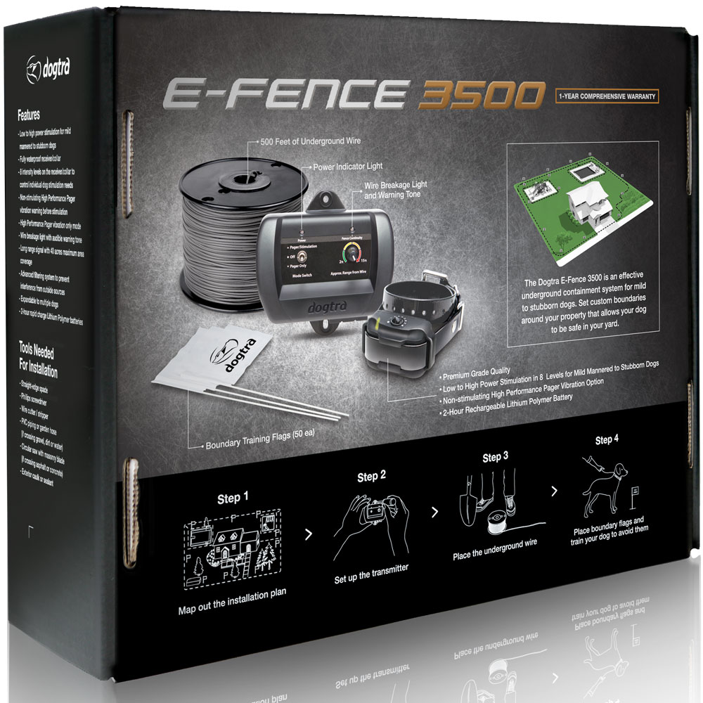
Dogtra E-FENCE 3500 Wired Fence Collar Containment System 40 Acres
Notice
All sales are Final. No returns or exchanges.
Description
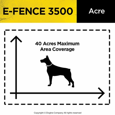
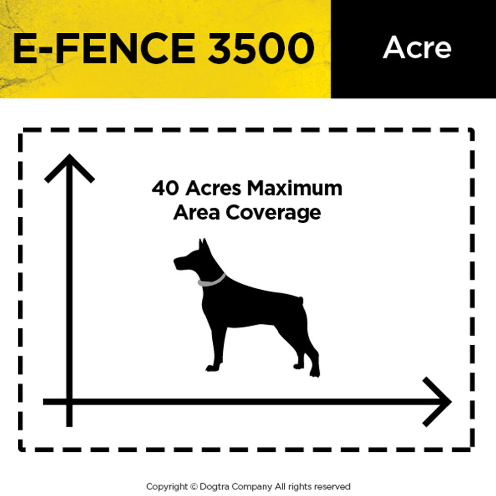
Dogtra E-Fence 3500 containment system allows dogs as small as 10 lbs. to run and play off leash without the expense and unattractive addition that goes along with installing a traditional fence. The EF-3500 containment system is designed to provide your dog with boundaries to keep him safe while still allowing him the freedom he needs. With a maximum coverage area of 40 acres, your dog will have plenty of room to roam.
Key Features:
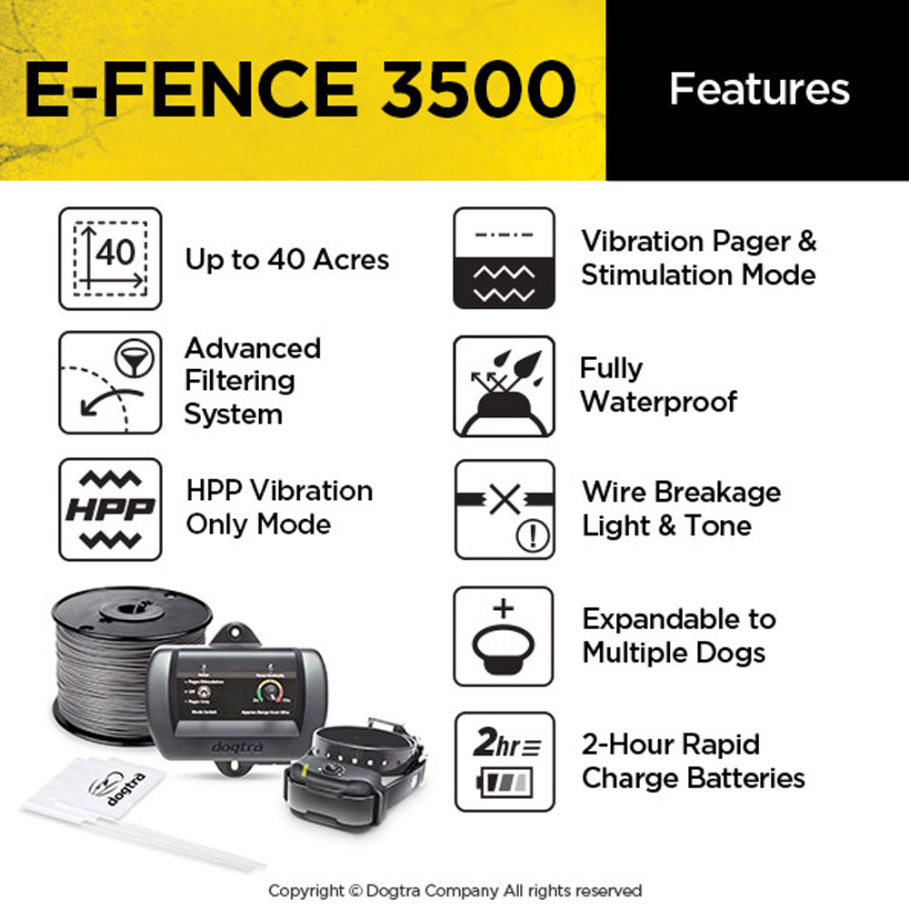
- Covers up to 40 acres
- Non-stimulating vibration to warn your dog prior to static stimulation
- Wire continuity indicator displays the status of the fence
- 8 levels of stimulation for each receiver collar
- Safety disconnect feature
- Add additional receiver collars available
- Designed for dogs as small as 10 lbs.
- Sleep mode activates when your dog is safely within the boundaries
- 2 hour quick charge Li-polymer batteries
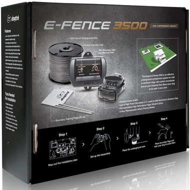
What's in the Dogtra E-FENCE 3500 Box:
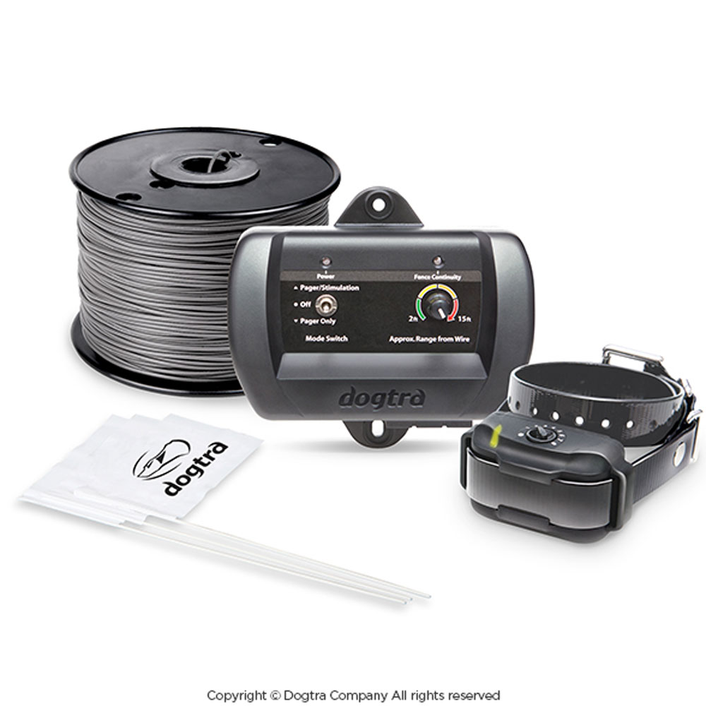
- Wall mountable transmitter
- Waterproof receiver collar
- Power adapter for transmitter
- Li-Polymer battery charger
- Magnetic power switch tool
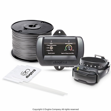
- 500 ft. of 18 gauge underground fence wire
- 50 training flags
- 4 waterproof splices
- Test light
- Grey ground wire
- Mounting screws and plastic anchors for transmitter
- Training probes
- ¾ inch long contact points
- Owner's manual
- Training manual
Useful Information
View Dogtra E-FENCE 3500 Owner's Manual.
View Dogtra E-FENCE 3500 Training Book.
Description of Transmitter Parts
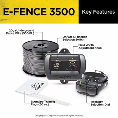
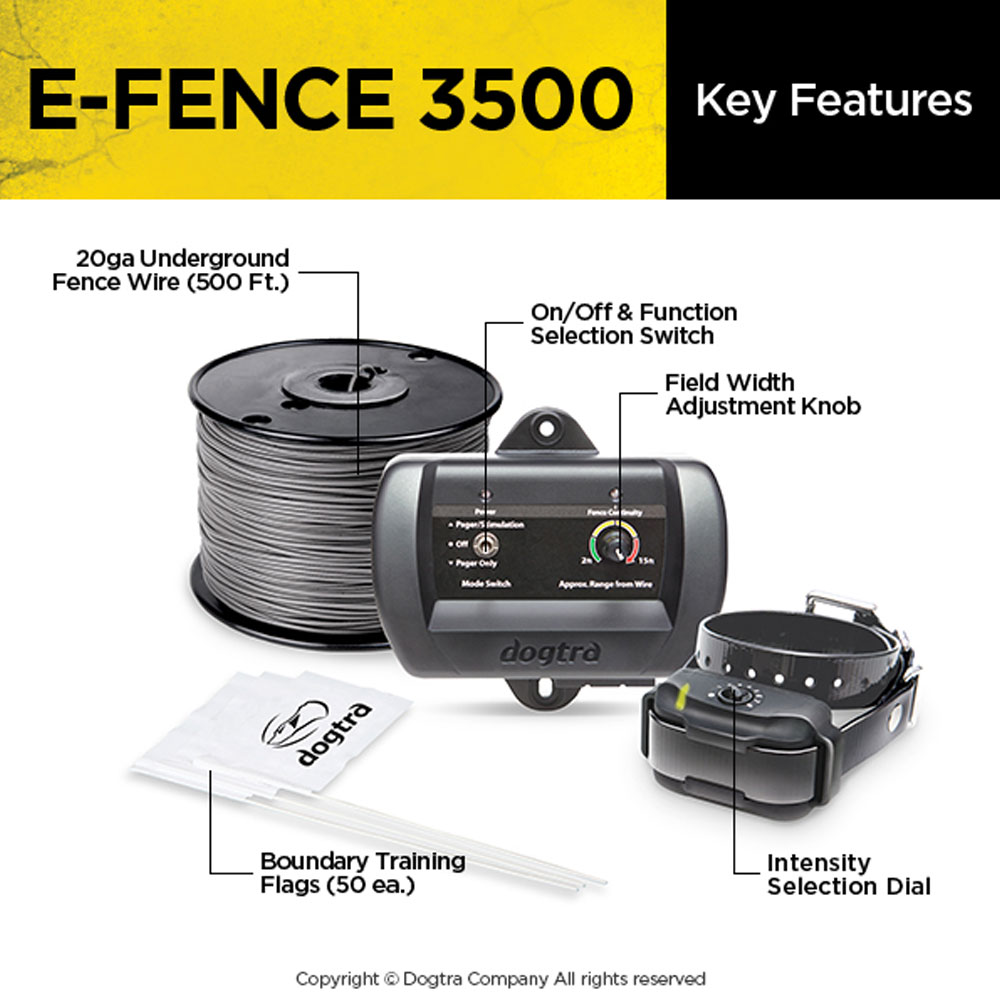
On/Off & Function Selection Switch

The On/Off & function selection switch has three functions. When the toggle switch is in the up position, the unit will give the dog a pager/vibration followed by stimulation correction. When the toggle switch is in the down position, only a pager/vibration occurs (no stimulation). The power is off when the toggle switch is set to the middle position.
Field Width Adjustment Knob

This knob controls the width of the signal field (the approximate distance from the boundary wire to the location where the receiver/collar first activates). Turning the knob clockwise increases the field width, giving your dog a wider area before the activation begins. Turning it counter-clockwise decreases the signal field, thusgiving the dog a shorter area prior to activation.
On/Off Indicator Light

When the On/Off & function selection switch is either in the up or down position the On/Off indicator light will be on, indicating that the power is on. When the switch is in the middle position the light goes off, indicating that the power is off.The indicator light stays on even if a fuse is blown.
Boundary Wire Continuity Light

When the wires are connected properly, the boundary wire continuity light will be on. In the event that the E-Fence 3500 wire becomes damaged or disconnected, the light will automatically turn off and the warning beep will sound.
Wire Connector Tabs

The easy-to-use push-release wire connectors let you instantly connect or disconnect the boundary wire leads. Wires should have the plastic coating stripped approximately a half-inch before being inserted into the red connectors on the bottom of the wall mount transmitter. The system come swith a ground wire to ground the unit. Strip about a half-inch on each end of the ground wire and insert one end into the black connector on the bottom of the wall transmitter. The other end should be buried into the ground or wrapped around a water pipe and secured with electrical tape.
Option: A lightning/surge protector can be purchased if there are no grounding options near the wall transmitter.
Power Jack

Plug the 120-volt adaptor into a 120-volt wall outlet and insert the adaptor plug into the power jack of the transmitter.
Wall-Mount Transmitter

Use the (2) included screws to mount the transmitter to a wallsecurely near an outlet. The unit will withstand freezing temperatures, but it is not waterproof. Therefore, we recommend mounting the transmitter in a safe, dry sheltered area such as a shed, garage or carport. Plastic anchors have been provided to secure mounting onto drywall. Use a ¼" drill bit to make holes into the drywall. Insert the anchors into the holes so that the open end faces out and mount the transmitter by inserting the screws into the open end of the anchors.To power the wall transmitter, plug the power adaptor into a standard 120-volt outlet and connect it to the power jack of the transmitter.
Description of Receiver/Collar Parts
Intensity Selection Dial

The stimulation level is adjustable from each individual dog's receiver/collar so that it is easy accommodate each dog's different personality and temperament. The stimulation levels range from level 1 to level 8, level 1being the lowest. In order to select the proper intensity level for each dog, we recommend that you begin at level 1 and continue to increase the level slowly until you are able to notice a reaction from your dog. This ensures that you select a level that is appropriate for your dog. When you place the knob at the Off position, the collar is completely shut off. In order to maintain full use of the batteries in the collar, please tun off the receiver/collar when your E-Fence 3500 system is not being utilized.
Receiver Indicator Light (LED)
When first activating the E-Fence 3500, the LED light on the receiver/collar will illuminate for approximately 1 second to indicate that the power is on. Once the unit is turned on, a blink will occur every 2 seconds to indicate that the receiver/collar is functioning properly. The color of the LED indicates the battery life of the receiver.
(Green = full charge, Amber = medium charge, Red = needs charge)
When the collar does not receive a signal from the transmitter for 10 seconds or more, the receiver/collar will go into sleep mode, and the LED light will stop blinking. When your dog gets close to the e-fence boundary wire, the indicator light will blink steadily to indicate that the receiver/collar is being activated.
PROPER FIT
The collar should be fitted so that the surgical stainless steel contact points press firmly against the dog's skin. You should be able to fit a finger in between the contact point and your dog's skin. The best location is either side of the dog's windpipe.
IMPROPER FIT
A loose fit can allow the collar to move around on the dog's neck. When this happens, the contact points may rub the skin and cause irritation. If the collar is too loose, electrical contact will be inconsistent and your corrections will be inconsistent also.Dogtra uses surgical stainless steel contact points and Anti-microbial plastic to protect the dog's skin.

ATTENTION!
Leaving the receiver/collar in the same location on the dog's neck for an extended period of time can cause skin irritation. If the dog is to wear the e-collar for long periods, occasionally reposition the collar so that the contact points are moved to a different location on the dog's neck. Make sure you check for skin irritation each time you use the unit.
Receiver/Collar Battery Charging Receptacle

On the inside of the receiver/collar, next to the collar strap, is a battery charging receptacle with a rubber plug.The unit will be fully waterproof with or without the rubber plug. If the dog was in salt-water, be sure to rinse the receiver and charging port with clean water, and let air dry.
Charging the Receiver/Collar
Dogtra uses Lithium-Polymerbatteries.
- Charge the unit before using the unit for the first time.
- Do not charge the batteries near any flammable substances.
- Fully charge the batteries if the unit is to be stored without use for a period of 3 months or more.
Recharge the unit if :
- The LED indicator light on the receiver/collar is emitting a red color.
- The indicator light on the receiver will not come on.
- The indicator light on the receiver comes on momentarily, but will not stay on near the wire.
Battery Charging Procedure
- Attach the charging cables to the receiver as shown.
- Plug the charger into a 120-volt wall outlet. When properly plugged in, all indicator lights should glow red. During the charging process, the unit will shut off.
- The Lithium-Polymer battery is fully charged within 2 hours. The lights will stay red during the charging process. The red light will change into a steady green light when the battery is fully charged. (When you disconnect the charger after finishing the charge, you will need to restart the units).
- After charging, cover the battery charging receptacle with therubber plug on the receiver/collar.
Note: Only use Dogtra-approved batteries, chargers, and accessories for the E-Fence 3500. Unauthorized chargers may cause the unit to malfunction and the indicator light to blink in an amber color.
How to Change the Length of the Contact Points
The Dogtra E-Fence 3500 comes equipped with standard ⅝" contact points that can be extended to ¾" contact points, for use with dogs with longer coats. To increase the contact point length from ⅝" to ¾", follow the steps below.
- Using the included adjustment tool with the side marked ⅝", unscrew the contact points counter-clockwise.
- Place the contact point extension over the exposed threads, flat sidedown.
- Place the contact points over the extensions and tighten the contactpoints and extensions clockwise using the adjustment tool with theside marked ¾".
Caution: Tighten until firmly in place. Be careful not to over tighten.
To shorten the contact points back to the standard ⅝", start with the adjustment tool with the side marked ¾", remove the contact point extensions, and tighten the contact points with the adjustment tool with the side marked ⅝".

Testing Your Dogtra E-Fence 3500 Priorto Installation

- To ensure that your E-Fence 3500 system is working properly, connect the power adaptor into the transmitter power jack and then plug the power adaptor into a household outlet. Switch the stimulation knob to Pager + Stimulation, or Pager Only. The On/Off indicator light should turn on.
- Unwind the length of ground wire that was provided and strip about ½ inch off each end. Insert both ends of the ground wire into the outer, red wire connector jacks, leaving the center jack free. If the wires are connected properly, the wire indicator light will be on.
- Next, activate the receiver/collar by turning the intensity level dial on the receiver to the desired level. The LED light will blink once every two seconds showing that it is on.
- Hold the receiver in your hand with the contact points facing up. Place the test lamp over the contact points and approach the test loop.
- Watch for the test lamp to come on and the unit to vibrate. Be careful not to touch the contact points as the unit will emit stimulation when activated.
* If not activated for 10 seconds or more, the system will go into sleep mode.
E-Fence 3500 Installation
Fence Wire - The fence wire must make a continuous loop around your property for your system to operate. The radio signal is delivered from the terminal of the transmitter, through the fence wire, and then back to the other terminal on the wall-mounted transmitter. When this is accomplished, the fence continuity light will emit a constant red light. Adversely, if you do not have wire continuity in your layout, the fence continuity light will turn off and an audible warning tone will emit from the transmitter.
Prior to burying your wire, test your containment system using your receiver to insure your system is working properly and the receiver activates. The wire should be buried approximately 4-6 inches into the ground or deep enough to protect it from being damaged by a lawnmower or any other machinery.

Wire Placement
CAUTION - Before you install your fence wire, contact the utility company to mark the utility lines on your property before you begin digging. Be sure to test your wire layout above ground before permanent installation begins. Carefully choose the areas in which you want to contain your dog. A diagram may be helpful in predicting unforeseen obstacles. (Please refer to the diagrams below.)
IMPORTANT!
When creating a Front Boundary Only, Fence Front Yard Only, or Front Boundary with Existing Fence type of design, THE TWO PARALLEL E-FENCE WIRES MUST BE 6-10 FEET APART to avoid any signal interference.
*Please note the diagrams are not drawn to scale. Single loop systems must keep 6-10 feet of distance between the wires as well.

The Dogtra EF-3500 containment system includes 500 feet of boundary wire and 50 training flags. Additional flags and wiring can be purchased through the Dogtra Company. The figures above are indicated for a rectangular layout. Actual flag/wire requirements may vary depending on the layout you've chosen.
Finding a Wire Break
- Go to the E-FENCE 3500 wall-mounted transmitter and disconnect the two boundary wire leads from the red connector tabs.
- Get the Underground Cable Wire Locator transmitter:
- Connect the red alligator clip to the end of one of the E-FENCE 3500 boundary wires.
- Connect the black alligator clip to the end of the ground wire that is not in the ground.
- Turn the Underground Cable Wire Locator transmitter from "OFF" to "Cable Scan" and leave the transmitter connected to the wires.
- Get the Underground Cable Wire Locator receiver and walk slowly along the path of the boundary wire. You should hear a whirling/static noise where the boundary wire is intact and no whirling noise where the break is located.
*Instructions based on the Noyafa NF-816-C Underground Cable Wire Locator. Other similar Underground Cable Wire Locators can be used as well to detect the breakage. However, the instructions may vary based on the Underground Cable Wire Locator used.
Fixing the Break
Once you have found the break, cut out the damaged area and use a weatherproof gel style wire splicer to reconnect the wires. If the break is large or if you cannot identify the break location, you may need to splice in some extra wire to bypass the area that is damaged.

